(Movie with classic BGM.)
Drive WS2812B with I2S
I tried to drive WS2812B from nRF52832 by SPI first, but it was tricky and sometimes failed to drive.
I saw a information who is drive WS2812B with I2S.
CONTROLLING WS2812B'S WITH I2S AND DMA ON THE ESP
I saw a information who is drive WS2812B with I2S.
CONTROLLING WS2812B'S WITH I2S AND DMA ON THE ESP
- It has many clock modes, and it can make 3.2MHz bit rate signals. The width of 4bit of this signal is 1.25 micro sec. and it is good for WS2812B drive.(Ref. CONFIG.MCKFREQ)
- I2S (with easyDMA) can send 16384 bytes in one transfer, it mens I can send the control data or 1365 LEDs at once. On the other hand SPI (with easyDMA) can send only 256 bytes at once, so I should make periodical transfer.(Ref. RXTXD.MAXCNT)
Then, I successfully controlled WS2812B LEDs array by nRF52832 I2S.
WS2812B control signal
The drive signals on WS2812B spec. is as follows.
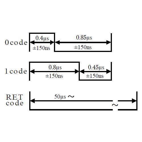
The width of 1bit with 3.2MHz signal is 312.5 nano sec.
So, we can make
0code with 312.5*1 of H and 312.5*3 of L signal, and
1code with 312.5*3 of H and 312.5*1 of H signal.
So, we can make
0code with 312.5*1 of H and 312.5*3 of L signal, and
1code with 312.5*3 of H and 312.5*1 of H signal.
Level converter IC(TXB0104)
Because the nRF52832 GPIO is 3.3V, and signal level of WS2812B is 5V, the level converter is required.. I used TXB0104 level converter. (The bi-direction level converter is not necessary for this purpose, so there will be more good solution.)
Harware
I wounded 4m LED tapes with 240 LEDs (60 per 1m) to empty dried seaweed case. 17 LEDs per 1 round. I put some bypass wiring for power as show in the photo.)- I used Nordic nRF52 DK.
- The drive signal P0..25 is connected to the LED drive signal via TXB0104.
- I used 5V 20A switching power unit during the development. And final program can drive by 5A 2A mobile battery.


Finally, I replaced bread board to Arduino Shiled style type like this,

Software
I uploaded the program to ghithub.
https://github.com/takafuminaka/nRF52832/tree/master/i2s_ws2812b_demostration_planB
(https://github.com/takafuminaka/nRF52832.git)
I used nRF5 SDK 11.0.0-2.alpha_bc3f6a.
The routines for WS2812B drive is in ws2812b_drive and i2s_ws2812b_drive dirtories.
In main.c, set RGB intense to array led_array_workm and call update routines periodically.
#define MAX_INTENSE (64) // Max intense of random LEDs for "flashing_random"
#define MAX_INTENSE2 (255) // Max intense of "shooting start" running bright LEDs for all demos.
#define MAX_INTENSE3 (64) // Max intense of "rainbow LEDs" for "running_rainbow" and "running_rainbowv" demos.
#define MIN_INTENSE (1) // Minimum intense of randaom LEDs for "flashing_random"
#define ROW_SIZE (17) // Count of LEDs for each round
#define CURRENT_LIMIT (1500) // Current limit of LEDs (mA)
#define FADE_IN_MS (6000) // Fade in/out period
https://github.com/takafuminaka/nRF52832/tree/master/i2s_ws2812b_demostration_planB
(https://github.com/takafuminaka/nRF52832.git)
I used nRF5 SDK 11.0.0-2.alpha_bc3f6a.
The routines for WS2812B drive is in ws2812b_drive and i2s_ws2812b_drive dirtories.
In main.c, set RGB intense to array led_array_workm and call update routines periodically.
Abstract of program
- Repeat of 3 demostratinos.
- Each demo processed followings in the loop
- Set the intense (0 to 255) of each RGB color; led_array[*].green, led_array[*].red, led_array[*].blue.
- ws2812b_drive_current_cap(led_array_work, NUM_LEDS, CURRENT_LIMIT); // Dim LEDs to match current limit.
- ws2812b_drive_dim(led_array, NUM_LEDS, dim); // Dim control for faed in and out.
- 2s_ws2812b_drive_xfer(led_array, NUM_LEDS, I2S_STDO_PIN); // Set color to LED array.
- nrf_delay_ms(DELAY_MS); // Delay
- Set color routine includes IS2 init, buffer memory allocation, and I2S uninit in one routine. It will be easy to use.
- But it will spend much CPU times for memory allocation and free for each update. So, if you'd like to make it more efficient by expanding this function.
- I refereed the current majoring report by uratan to create current limit dimmer function. The program set was 1.5A and the majored was 1.3A in the movie. It works well.
Parmeters
file project.h
#define NUM_LEDS (240) // Number of LEDs#define MAX_INTENSE (64) // Max intense of random LEDs for "flashing_random"
#define MAX_INTENSE2 (255) // Max intense of "shooting start" running bright LEDs for all demos.
#define MAX_INTENSE3 (64) // Max intense of "rainbow LEDs" for "running_rainbow" and "running_rainbowv" demos.
#define MIN_INTENSE (1) // Minimum intense of randaom LEDs for "flashing_random"
#define ROW_SIZE (17) // Count of LEDs for each round
#define CURRENT_LIMIT (1500) // Current limit of LEDs (mA)
#define FADE_IN_MS (6000) // Fade in/out period
0 件のコメント:
コメントを投稿